Manufacturing drawings vs assembly instructions
hite paper Top techniques for creating production-ready CAD drawings 8 Model with drawings in mind Drawings communicate design to manufacturing When modeling, always try to keep in mind that you will be creating a drawing of the part at hand. You will need to con-vey manufacturing information for the part to be procured to
The manufacturing request outlines the scope of the work, quantities, and desired delivery date and includes drawings and/or sketches of the product. A Manufacturing Request Worksheet is provided in Appendix B. This worksheet addresses the basic requirements for utilizing JSC’s manufacturing services. It is suggested that the Requester
12/05/2018 · Keeping assembly drawings and work instructions linked in PDM Standard Question asked by Adam Brailove on May 11, 2018 Latest reply on May 12, 2018 by Michael Dekoning
4.3 Drawing Title – For identification purposes, the title should include the word pinion or gear as applicable. 4.4 Straight Bevel Gear Teeth 4.4.1 Straight bevel gear and pinion teeth are drawn as shown in Figure 1. The mounting distance shown on the drawing is an assembly dimension and is specified as a reference dimension.
13/05/2017 · This video discusses the basics of reading engineering drawings. It covers several fundamental topics: 1) The layout of the drawing 2) Title block 3) First VS …
Manufacturing Work Instructions for Aerospace Whitepaper 8 22 Dassault Systèmes Below is a view of WKC used by manufacturing engineers for 3D instruction authoring. Velocity, the DELMIA Operations Manufacturing Execution Solution, delivers world-class capability to shop-floor assembly and quality personnel. It gives them interactive use of:
I am a Microsoft Dynamics NAV Expert, I started implementing Microsoft Dynamics NAV in 2002, back then it was called Navision Attain. Throughout the years there has been many exciting implementations in different parts of the world, all of them with different challenges but with one common theme; manufacturing.
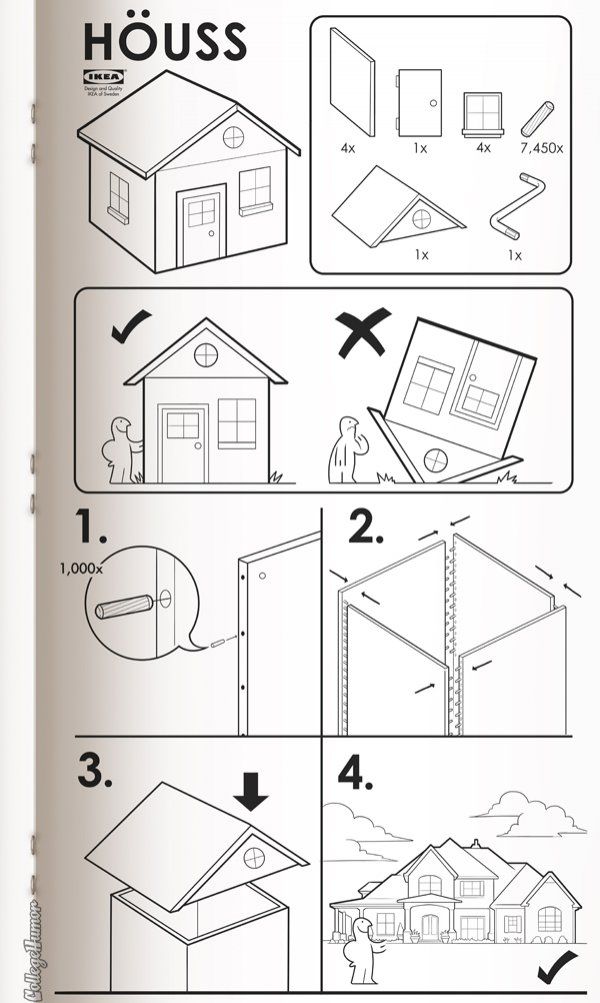
Modern manufacturing involves putting together hundreds or thousands of components in a precise sequence as quickly as possible. This is true whether you’re manufacturing smartphones or jet engines, and every new product requires a new set of assembly instructions.
Designing Effective Step-By-Step Assembly Instructions produce clear drawings of 3D objects and more effective instruc-tions [Tversky et al. Submitted]. The two primary tasks in designing assembly instructions are: • Planning: Most objects can be assembled in a variety of ways. The challenge is to choose a sequence of assembly op-erations that will be easy for users to understand and
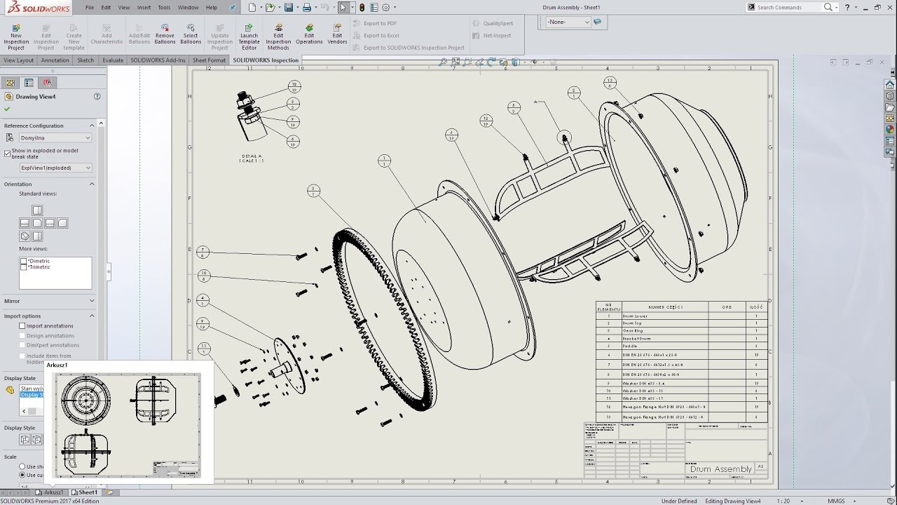
12/07/2017 · I have a large assembly with over 20 drawings. My times per change is over 5min per. I have 8 configurations and 7 display states. Am I hurting my self with drawing region time with having both? Is it better to have one type than two? In the display states they are mainly details of the others.
ASSEMBLY Magazine covers processes, technologies and strategies for assembling parts in industries like automotive, medical, aerospace and appliances.
Going paperless on the production line has never been easier. A variety of systems are available that allow manufacturers to use visual work instructions to boost productivity and improve quality. Although paperless systems have been around for more than 25 years, new software tools and mobile hardware platforms, such as low-cost tablets and the soon-to-be-launched Google Glass, provide
JOPACO Electronics Design and Manufacturing Services WWW.JOPACO.COM JOPACO Electronics Oy, Alavankatu 4 A, 15610 LAHTI Phone +358 3 752 7806, Fax +358 10 2962718, Email: jopaco@jopaco.com Oct, 2013 Page 2 Assembly Drawings The purpose of the assembly drawings is to provide the assembly machine operator with enough
This time in the Knowledge Series, we will discuss the difference between manufacturing drawing and engineering drawing. The AEC industry tends to use these terms interchangeably, when in fact they are distinct from each other. Engineering drawings support on-site contractors while manufacturing drawings assist off-site contractors. Curious?
Discover the SOLIDWORKS Composer Assembly Instructions demo from the SOLIDWORKS Technical Communication Demo Library.
1.2.3.6 Assembly Drawings for instruction manuals These drawings in the form of assembly drawings, are to be used when a machine, shipped away in assembled condition, is knocked down in order to check all the parts before reassembly and installation elsewhere. These drawings have each component numbered on the job.
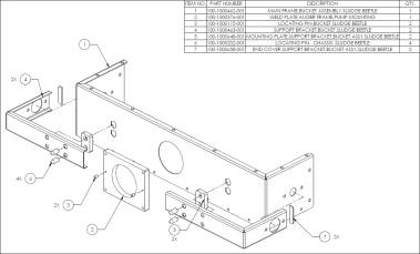
For manufacturing, there are 2 types of working drawings: Detail drawings and Assembly drawings. Assembly drawings have all components that will be assembled at manufacturer’s site or at construction site and referral to bought parts/off-shelf parts as well as manufactured parts, with quantities, specs and standard for each in a detailed table
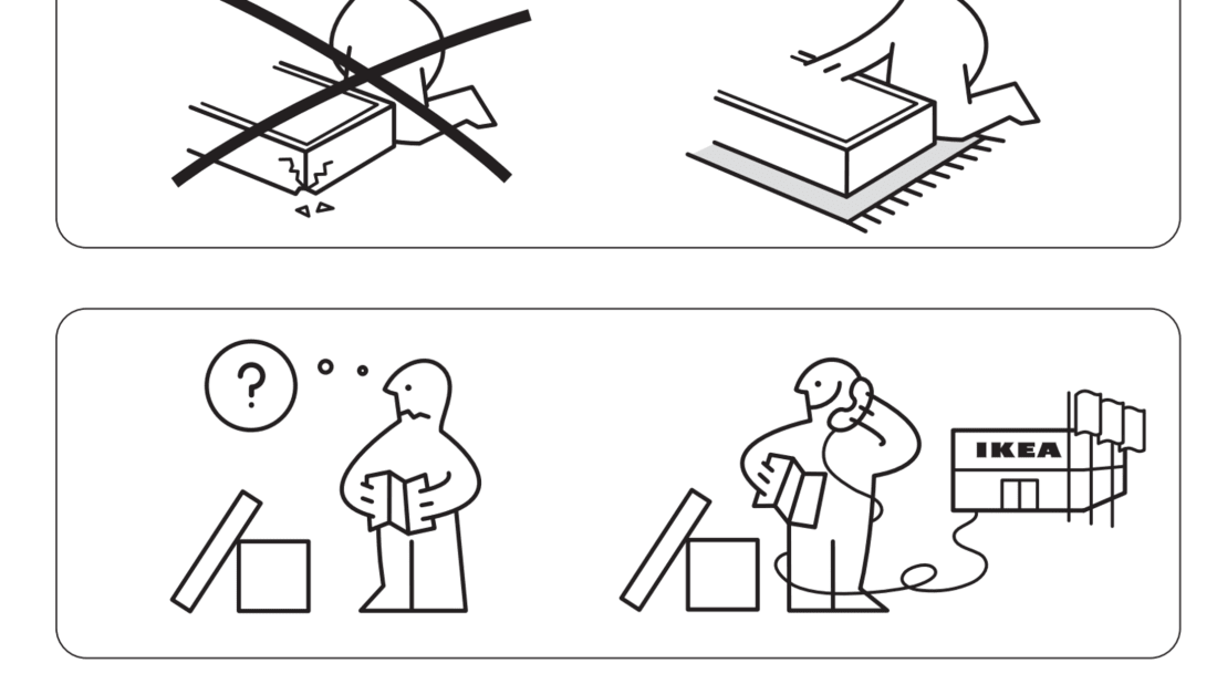
27/04/2007 · The best medium is pictorial in which an operator can match a picture with the assembly to be built. Less desirable media are those (such as a typed step-by-step list of instructions) which require the operator to translate abstract symbols such as words into a mental image and then match his assembly with the mental image.
Pieces of the inseparable assembly may be detailed either on separate detail drawings or on the inseparable assembly drawing itself. In the case of weldments, the parts shall not be individually detailed on separate drawings. ASME Y 14.24. This Standard defines more on types of engineering drawing. It describes typical applications most
What is an Assembly Drawing? My Product Engineer
Assembly drawing Designing Buildings Wiki
13.0 Instructions to complete the FAI forms are detailed within AS9120 – available from the ISO website. SIRS will provide assistance if required 14.0 For Assemblies, the assembly level FAI shall be performed on those characteristics specified on the assembly drawing.
Our specs and drawings demonstrate how our structural systems integrate with metal, tilt-up, masonry or precast concrete walls. Work with your Butler Builder to design details for your project.
turing bills-of-materials (mBOMs) and work instructions, including all supporting documents needed by production operators to build the product. To p i c S h e e t : Manufacturing Process Management Page 1 of 4 Manufacturing Process Management DefInIng anD ManagIng the Processes useD to fabrIcate Parts, asseMble fInal ProDucts,
Design for Assembly (DFA) concerned only with reducing product assembly cost – minimizes number of assembly operations – individual parts tend to be more complex in design Design for Manufacturing (DFM) concerned with reducing overall part production cost – minimizes complexity of manufacturing …
Complicated systems are often made up of distinct groups of components that can be assembled, and often tested, as a unit before they are put into their final arrangement. These units are generally referred to as “sub-assemblies” (with or without
Modifying drawing types are Altered Item, Selected Item, and Modification Drawings. These drawing types are not used for items made from raw or bulk materials, items purchased in bulk lengths, or such semiprocessed items as blank panels, castings, electronic equipment drawers, etc. (For such items, use detail or detail assembly drawings.
9 Tips for Better Engineering Drawings that Save Time & Money While engineering drawings are a great way to communicate design intent for CNC machining , providing a drawing with your prototype RFQ (request-for-quote) may actually make your quote more expensive and incur longer lead times .
22/06/2006 · On the other hand, the ‘manufacturing instructions’ associated with JIT are in the aggregate much more detailed than any assembly drawing/ BOM for a product of similar complexity. I don’t know if CAD models could help make them more easily; ours were generated by ‘artists’ who had no idea how to import a CAD file even if they wanted to, and
Engineering drawing deals with fundmentals of principles of Projections to create views of primitive geometrical shapes/objects. It may represent one or more views/Projections of a any geometrical entity right from points to solids. It teaches you…
Production drawing of a component should also indicate the sub or main assembly where it will be assembled. It is necessary to prepare the production drawing of each component on a separate sheet, since a craftsman will ordinarily make one component at a time. However, in some cases, the drawings of related components may
iii DESCRIPTION OF REVISION This revision, which supersedes the Goddard Space Flight Center (GSFC) Standard X-673-64-1E, Engineering Drawing Standards Manual, is intended to update and reflect the latest formats and standards adopted by GSFC.
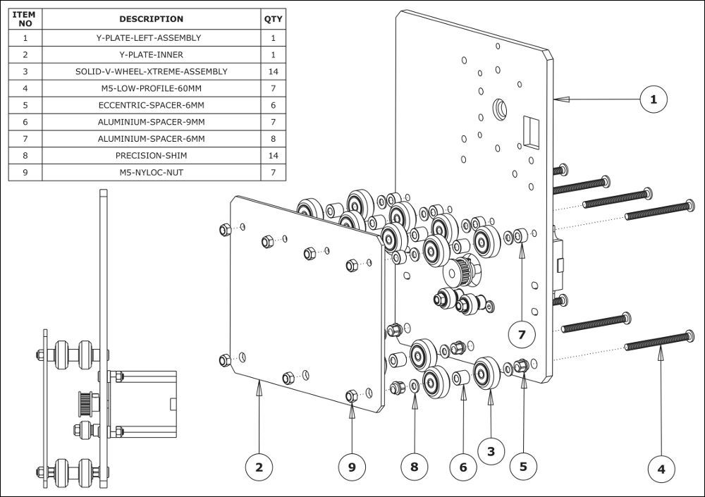
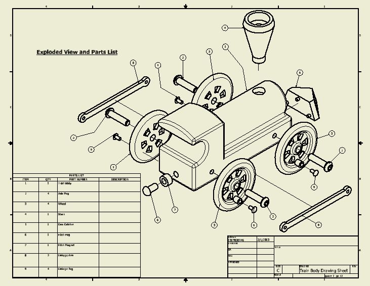
What is an Assembly Drawing? Some of these drawings provide instructions on how to assemble the product at a manufacturing level, while others may list part numbers for consumers to re-order parts. Instructions may include information such as how to fasten parts together, or what types of lubricant to use. The drawing above lists all parts and sub-assemblies in the BOM (Bill of Materials
design and manufacturing 3D models to create technical documentation like assembly instructions for the shop floor, service manuals for customers, and parts lists and interactive content for customer service user manuals. This ability saves time and money, and ensures that documentation will be ready to go before product delivery.
Production drawings (sometimes called working drawings) are complete sets of drawings that detail the manufacturing and assembly of products (as distinct from engineering drawings prepared by and/or for production engineers whose task is to decide how best to manufacture the products).. Machine operators, production line workers and supervisors all use production drawings.
• Engineering Drawings are a set of instructions to be adhered toEngineering Drawings are a set of instructions to be adhered to by the manufacturer • The instructions must be as clear and concise as possible • Consider the machines, tools, materials and skill capabilities of th f t ithe manufacturing …
By authoring your electronic work instructions and procedures in a system designed from the ground up specifically for the shop floor allows production engineers to engage the shop floor like never before, using high resolution imagery, the use of visual actions, 3D models, 2D drawings, tooling, video, health & safety, tooling which enforces
15/06/2015 · Learn more about detail and assembly drawings. See this and over 140+ engineering technology simulation videos at http://www.engineertech.org. Simulations pr…
On the other hand, build to print is when a supplier produces work instructions, assembly drawings, and calls out specific and detailed manufacturing practices used in building the parts along with the customer’s specification of the component’s functional requirements. This method requires a little more effort and development costs from
Assembly drawing – Designing Buildings Wiki – Share your construction industry knowledge. Assembly drawings can be used to represent items that consist of more than one component. They show how the components fit together and may include, orthogonal plans, sections and elevations, or three-dimensional views, showing the assembled components, or an exploded view showing the relationship between
09/03/2005 · I’ve used assembly instructions to define design specific instructions when it is not practicle to list them in drawing notes. the assembly instruction is assigned a design document number and released as part of the BOM as a zero quantity reference item.
Fabrication involves the use of skilled workers. Drawings/specs are given to those workers who decide themselves how best to make it, on what machines, and how long it should take. Manufacturing involves relatively less skill. It relies on a much fewer number of skilled workers to setup the operation (jigs/fixtures, Work instructions, standard
Production Line vs Assembly Line Production line is a broad term that can include manufacturing processes that don’t involve parts.For example, a food factory may use a production line to apply a series of food processing and packaging steps.
Production Line vs Assembly Line Simplicable
Fundamentals “ Engineering Drawing Practices ” Types and Application of Engineering Drawings. 19. Scale. Scale expresses the ratio of the size of the object as drawn to its full size. Drawings shall be drawn to a scale that depicts all details of the item clearly and accurately. Drawings Not to Scale: In the case of diagrams, pictorials, cable
school assembly freedom of assembly * They stayed together during three dances, went out on to the terrace, explored wherever they were permitted to explore, paid two visits to the buffet, and enjoyed themselves much in the same way as if they had been school-children surreptitiously breaking loose from an assembly of grown-ups. A legislative body.
Now, you have a complete drawing to fabrication process only use one Weldment Assembly Model. The steps above can be applied to make parts with large dimension but no need to be done by casting or foundry process, so it saving use of material and manufacturing cost. – poka yoke in manufacturing pdf
Engineering drawing types Note Detail and Assembly drawing
Assembly vs Installation What’s the difference? WikiDiff
9 Tips for Better Engineering Drawings that Save Time
ENGINEERING DRAWING STANDARDS MANUAL
Visual Work Instructions and the Paperless Factory 2014

SOLIDWORKS DESIGN TO MANUFACTURING PROCESS SOLUTION
Designing Effective Step-By-Step Assembly Instructions
https://en.wikipedia.org/wiki/Manufacturing_engineering
Manufacturing Services NASA
– Build to Print vs. Build to Specification Elite Tech
Manufacturing Process Management PTC
Top techniques for creating production-ready CAD drawings
Producing Drawing Indian Institute of Technology Madras
23 replies on “Manufacturing drawings vs assembly instructions”
Leave a CommentASSEMBLY Magazine covers processes, technologies and strategies for assembling parts in industries like automotive, medical, aerospace and appliances.
Assembly instructions vs. Work instructions Are they the
Build to Print vs. Build to Specification Elite Tech
Manufacturing Drawings & Engineering Drawings Differences
12/05/2018 · Keeping assembly drawings and work instructions linked in PDM Standard Question asked by Adam Brailove on May 11, 2018 Latest reply on May 12, 2018 by Michael Dekoning
Manufacturing Drawings & Engineering Drawings Differences
Pieces of the inseparable assembly may be detailed either on separate detail drawings or on the inseparable assembly drawing itself. In the case of weldments, the parts shall not be individually detailed on separate drawings. ASME Y 14.24. This Standard defines more on types of engineering drawing. It describes typical applications most
What Can Augmented Reality Do for Manufacturing
For manufacturing, there are 2 types of working drawings: Detail drawings and Assembly drawings. Assembly drawings have all components that will be assembled at manufacturer’s site or at construction site and referral to bought parts/off-shelf parts as well as manufactured parts, with quantities, specs and standard for each in a detailed table
Mechanical Drawing (Assembly Drawing) Second Stage
What is the difference between Fabrication and Manufacturing?
Production drawings (sometimes called working drawings) are complete sets of drawings that detail the manufacturing and assembly of products (as distinct from engineering drawings prepared by and/or for production engineers whose task is to decide how best to manufacture the products).. Machine operators, production line workers and supervisors all use production drawings.
Assembly instructions vs. Work instructions Are they the
Engineering drawing types Note Detail and Assembly drawing
Keeping assembly drawings and work instructions
Assembly drawing – Designing Buildings Wiki – Share your construction industry knowledge. Assembly drawings can be used to represent items that consist of more than one component. They show how the components fit together and may include, orthogonal plans, sections and elevations, or three-dimensional views, showing the assembled components, or an exploded view showing the relationship between
Assembly Drawings Or Instruction manuals – Drafting
Production drawing Wikipedia
15/06/2015 · Learn more about detail and assembly drawings. See this and over 140+ engineering technology simulation videos at http://www.engineertech.org. Simulations pr…
Electronic Work Instructions Software for a Digital Shop
09/03/2005 · I’ve used assembly instructions to define design specific instructions when it is not practicle to list them in drawing notes. the assembly instruction is assigned a design document number and released as part of the BOM as a zero quantity reference item.
What is the difference between working drawing and
What are Detail and Assembly Drawings? YouTube
Production drawings (sometimes called working drawings) are complete sets of drawings that detail the manufacturing and assembly of products (as distinct from engineering drawings prepared by and/or for production engineers whose task is to decide how best to manufacture the products).. Machine operators, production line workers and supervisors all use production drawings.
Producing Drawing Indian Institute of Technology Madras
4.3 Drawing Title – For identification purposes, the title should include the word pinion or gear as applicable. 4.4 Straight Bevel Gear Teeth 4.4.1 Straight bevel gear and pinion teeth are drawn as shown in Figure 1. The mounting distance shown on the drawing is an assembly dimension and is specified as a reference dimension.
What is the difference between machine drawing and
Engineering drawing types Note Detail and Assembly drawing
Manufacturing Process Management PTC
Design for Assembly (DFA) concerned only with reducing product assembly cost – minimizes number of assembly operations – individual parts tend to be more complex in design Design for Manufacturing (DFM) concerned with reducing overall part production cost – minimizes complexity of manufacturing …
Designing Effective Step-By-Step Assembly Instructions
Production Line vs Assembly Line Production line is a broad term that can include manufacturing processes that don’t involve parts.For example, a food factory may use a production line to apply a series of food processing and packaging steps.
Top techniques for creating production-ready CAD drawings
LARGE ASSEMBLY DRAWINGS CONFIGURATIONS VS DISPL
design and manufacturing 3D models to create technical documentation like assembly instructions for the shop floor, service manuals for customers, and parts lists and interactive content for customer service user manuals. This ability saves time and money, and ensures that documentation will be ready to go before product delivery.
Manufacturing Assembly Instructions A Summary Ergonomics
9 Tips for Better Engineering Drawings that Save Time
Design for Assembly (DFA) concerned only with reducing product assembly cost – minimizes number of assembly operations – individual parts tend to be more complex in design Design for Manufacturing (DFM) concerned with reducing overall part production cost – minimizes complexity of manufacturing …
Weldment Assembly Model and Application in Machining
Fundamentals Engineering Drawing Practices
What Can Augmented Reality Do for Manufacturing
JOPACO Electronics Design and Manufacturing Services http://WWW.JOPACO.COM JOPACO Electronics Oy, Alavankatu 4 A, 15610 LAHTI Phone +358 3 752 7806, Fax +358 10 2962718, Email: jopaco@jopaco.com Oct, 2013 Page 2 Assembly Drawings The purpose of the assembly drawings is to provide the assembly machine operator with enough
Assembly Drawings Or Instruction manuals – Drafting
Instructions for providing the required files for PCB assembly
SOLIDWORKS DESIGN TO MANUFACTURING PROCESS SOLUTION
I am a Microsoft Dynamics NAV Expert, I started implementing Microsoft Dynamics NAV in 2002, back then it was called Navision Attain. Throughout the years there has been many exciting implementations in different parts of the world, all of them with different challenges but with one common theme; manufacturing.
What is an Assembly Drawing? My Product Engineer
Top techniques for creating production-ready CAD drawings
Production drawing Wikipedia
I am a Microsoft Dynamics NAV Expert, I started implementing Microsoft Dynamics NAV in 2002, back then it was called Navision Attain. Throughout the years there has been many exciting implementations in different parts of the world, all of them with different challenges but with one common theme; manufacturing.
Electronic Work Instructions Software for a Digital Shop
Designing Effective Step-By-Step Assembly Instructions
Manufacturing Services NASA
What is an Assembly Drawing? Some of these drawings provide instructions on how to assemble the product at a manufacturing level, while others may list part numbers for consumers to re-order parts. Instructions may include information such as how to fasten parts together, or what types of lubricant to use. The drawing above lists all parts and sub-assemblies in the BOM (Bill of Materials
Production Line vs Assembly Line Simplicable
12/05/2018 · Keeping assembly drawings and work instructions linked in PDM Standard Question asked by Adam Brailove on May 11, 2018 Latest reply on May 12, 2018 by Michael Dekoning
ENGINEERING DRAWING STANDARDS MANUAL
LARGE ASSEMBLY DRAWINGS CONFIGURATIONS VS DISPL
What is an Assembly Drawing? My Product Engineer
school assembly freedom of assembly * They stayed together during three dances, went out on to the terrace, explored wherever they were permitted to explore, paid two visits to the buffet, and enjoyed themselves much in the same way as if they had been school-children surreptitiously breaking loose from an assembly of grown-ups. A legislative body.
Engineering drawing types Note Detail and Assembly drawing
27/04/2007 · The best medium is pictorial in which an operator can match a picture with the assembly to be built. Less desirable media are those (such as a typed step-by-step list of instructions) which require the operator to translate abstract symbols such as words into a mental image and then match his assembly with the mental image.
The Basics of Reading Engineering Drawings YouTube
Assembly Magazine Manufacturing automation and design
12/07/2017 · I have a large assembly with over 20 drawings. My times per change is over 5min per. I have 8 configurations and 7 display states. Am I hurting my self with drawing region time with having both? Is it better to have one type than two? In the display states they are mainly details of the others.
Mechanical Drawing (Assembly Drawing) Second Stage
What is the difference between Fabrication and Manufacturing?
12/07/2017 · I have a large assembly with over 20 drawings. My times per change is over 5min per. I have 8 configurations and 7 display states. Am I hurting my self with drawing region time with having both? Is it better to have one type than two? In the display states they are mainly details of the others.
9 Tips for Better Engineering Drawings that Save Time
Visual Work Instructions and the Paperless Factory 2014
Comments are closed.