Mechanical engineering manufacturing drawing pdf
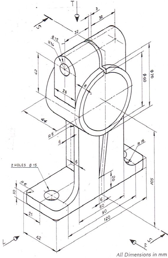
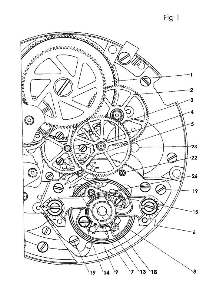
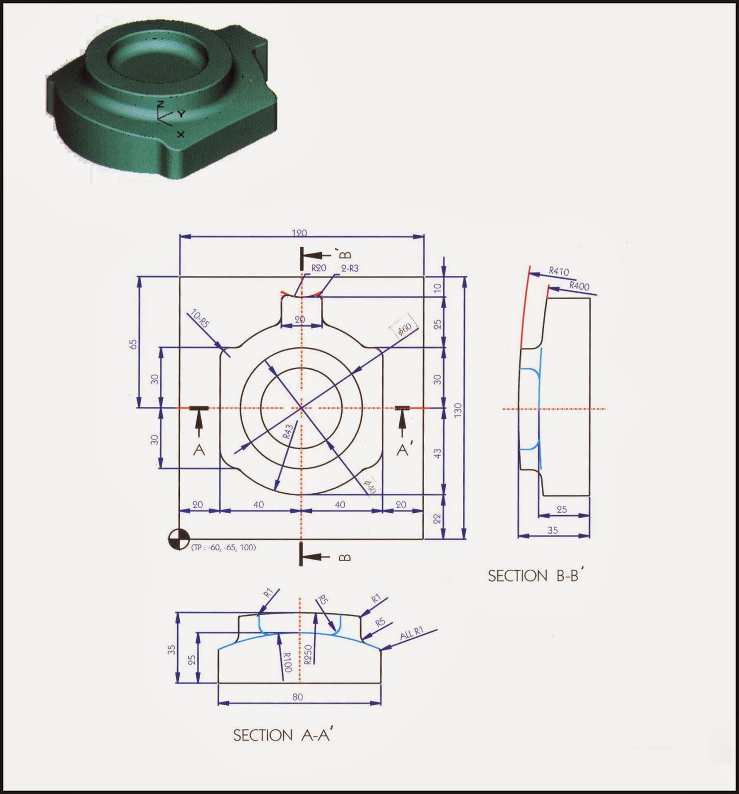
The engineering drawing set is produced by the Engineering department, and is the final output of the research, design and development phase of a project. The engineering drawing set includes schematics, printed circuit board layouts, bills of material, drawings for mechanical parts and assembly drawings. The engineering drawings set is a complete specification of what the finished product is
Mechanical engineering courses develop your ability to design and create mechanical systems, including those used in the automotive, aeronautics, robotics, and manufacturing industries. Subtopics include mechanics, fluid dynamics, heat transfer, and more.
The qualification has been developed with manufacturing and engineering-related industry sectors as a focus and may be packaged to meet the specific needs of drafting in mechanical and machine construction and maintenance, steel fabrication, other fabrication services and assembly, mechanical services, electrical services, fluid power, piping assembly, and so on.
manufacturing. • Parts with small tolerances often require greater inspection and call for the rejection of parts ÆGreater Quality Inspection ÆGreater cost. • Do not specify a smaller tolerance than is necessary! Department of Mechanical Engineering and Mechanics How are Tolerances Specified •Size – Limits specifying the allowed variation in each dimension (length, width, height
Drawing Standards. Conventions are essential for clear, unambiguous written, oral, and graphical communication. Drawings are used by engineers and manufacturing technologists to communicate their ideas and hence good engineering drawings follow conventions which are referred to as drawing standards.
published by ASME that cover various aspects of mechanical drawings, here are a few of them… • ASME Y14.100 -2004 Engineering Drawing Practices • ASME Y14.4M – 1989 Pictorial Drawing • ASME Y14.3M – Multi and Sectional View Drawings • ASME Y14.1 – 1995 Decimal Inch Drawing Sheet Size and Format • ASME Y14.5M – 1994 Geometric Dimensioning and Tolerancing • ASME …
MEM09208A Detail fasteners and locking devices in mechanical drawings Modification History ReleaseUnit Descriptor 1 – New unit of competency This unit of competency covers the skills and knowledge required to produce detailed engineering drawings containing fastening and locking devices. Applicationpredeterminedof the Unit This unit is suitable for those working within a drafting work
Mechanical Engineering Projects Solidworks Tutorial Autocad 3d Sketch Cad Drawing Tool Design 3d Design Drawing Practice Science You can generate drawings in SolidWorks the same way you would generate them in drafting and drawing systems. However, creating models and generating drawings from the model have many advantages; for example: Designing models. Tekin AÇIKGÖZ. Eğitim. …
Mechanical engineering and related drawings shall be created in millimetres. Civil Civil engineering, layouts and installation drawings may be created in meters.
concrete ceiling of the Mechanical Engineering Drawing Office, (room S319 building J07). The aspiration was of course to follow in the footsteps of Michelangelo Buanarroti and his work on the ceiling of the Sistine Chapel.
Engineering Drawings and Designs CAD/CAM Engineering

Lecture Notes Design and Manufacturing I Mechanical
A list of mechanical engineering software, including computer aided design (CAD) and computer aided manufacturing (CAM) software.
Mechanical engineering is the discipline that applies the principles of engineering, physics, and materials science for the design, analysis, manufacturing, and maintenance of mechanical systems. It is the branch of engineering that involves the design, production, and operation of machinery.
of common engineering materials and how to select them for a given design and familiar with the link between product design, material selection and manufacturing.
Source URL: http://ocw.mit.edu/courses/mechanical-engineering/2-007-design-and-manufacturing-i-spring-2009/related-resources/drawing_and_sketching/
Geometric tolerancing reading is very important to understand detailed drawings. It helps to read drawings for engineers, designers, manufacturers etc. Geometric tolerancing reading helps to understand to specify and control…
See more: 17 PDF Drawings that I need re-drafted in AutoCAD, I need a CAD made from my 2D drawings, i need an artist to create line drawings og existing paintings, mechanical engineering, solidworks, engineering drawing, i need a good graphinc designer in ireland to vector drawings for t shirt designs, i need cad drawings done, i need a good pr person for my artwork drawings, i need …
Manufacturing Process, Engineering Mechanics, Mechatronics, Robotics, Advance Methods of Manufacturing and Management of Manufacturing System at Undergraduate course. He …
design, drafting, mechanical, manufacturing, production, tool/gage, quality, process and project engineers, CAD/CAM/CAE specialists, inspectors and educators across a broad range of global manufacturing.
manufacturing, mechatronic, or naval engineering) you choose to pursue in the future. Today’s engineering problem is becoming too complex to be addressed by a single engineer based on separate disciplinary knowledge.
Limits & Fits. At the end of this presentation, the students should be able to : Explain the necessity for tolerancing. Identify the symbols used for fundamental deviation. Identify the numbers used for grades of tolerances. Select fits for mating components. Translate limits and fits symbols to engineering drawings using BS4500A.

MORAINE VALLEY COMMUNITY COLLEGE Revision:May 11, 2010 Engineering Drawing & CAD Standards Mechanical Design/CAD Program C. Bales, M. Vlamakis
Engineering Drawings and Designs I am looking for a freelancing mechanical engineer who can work with Solid Works and Autodesk Inventor software for drawing and designing work on a free lancing basis .

Mechanical Engineering Drawings Pinterest
– manufacturing process in engineering mcq questions bank pdf download
Engineering Desing Manufacturing
Mechanical Engineering CAD CAM Automation

Limits & Fits.pdf Engineering Tolerance Mechanical


https://en.m.wikipedia.org/wiki/Engineering_tolerance
chemistry and manufacture of cosmetics science 4th edition pdf –
18 replies on “Mechanical engineering manufacturing drawing pdf”
Leave a Commentpublished by ASME that cover various aspects of mechanical drawings, here are a few of them… • ASME Y14.100 -2004 Engineering Drawing Practices • ASME Y14.4M – 1989 Pictorial Drawing • ASME Y14.3M – Multi and Sectional View Drawings • ASME Y14.1 – 1995 Decimal Inch Drawing Sheet Size and Format • ASME Y14.5M – 1994 Geometric Dimensioning and Tolerancing • ASME …
Engineering Drawings and Designs CAD/CAM Engineering
MEM09208A Detail fasteners and locking devices in mechanical drawings Modification History ReleaseUnit Descriptor 1 – New unit of competency This unit of competency covers the skills and knowledge required to produce detailed engineering drawings containing fastening and locking devices. Applicationpredeterminedof the Unit This unit is suitable for those working within a drafting work
Engineering Desing Manufacturing
training.gov.au MEM40412 – Certificate IV in Engineering
MORAINE VALLEY COMMUNITY COLLEGE Revision:May 11, 2010 Engineering Drawing & CAD Standards Mechanical Design/CAD Program C. Bales, M. Vlamakis
SolidWorks Fabrications Drawings CAD/CAM Manufacturing
Mechanical engineering courses develop your ability to design and create mechanical systems, including those used in the automotive, aeronautics, robotics, and manufacturing industries. Subtopics include mechanics, fluid dynamics, heat transfer, and more.
Limits & Fits.pdf Engineering Tolerance Mechanical
Mechanical engineering is the discipline that applies the principles of engineering, physics, and materials science for the design, analysis, manufacturing, and maintenance of mechanical systems. It is the branch of engineering that involves the design, production, and operation of machinery.
Engineering Desing Manufacturing
Mechanical Engineering CAD CAM Automation
training.gov.au MEM40412 – Certificate IV in Engineering
The engineering drawing set is produced by the Engineering department, and is the final output of the research, design and development phase of a project. The engineering drawing set includes schematics, printed circuit board layouts, bills of material, drawings for mechanical parts and assembly drawings. The engineering drawings set is a complete specification of what the finished product is
Lecture Notes Design and Manufacturing I Mechanical
Engineering Desing Manufacturing
Mechanical Engineering Drawings Pinterest
The qualification has been developed with manufacturing and engineering-related industry sectors as a focus and may be packaged to meet the specific needs of drafting in mechanical and machine construction and maintenance, steel fabrication, other fabrication services and assembly, mechanical services, electrical services, fluid power, piping assembly, and so on.
Lecture Notes Design and Manufacturing I Mechanical
SolidWorks Fabrications Drawings CAD/CAM Manufacturing
Mechanical Engineering CAD CAM Automation
Mechanical engineering is the discipline that applies the principles of engineering, physics, and materials science for the design, analysis, manufacturing, and maintenance of mechanical systems. It is the branch of engineering that involves the design, production, and operation of machinery.
Engineering Drawings and Designs CAD/CAM Engineering
SolidWorks Fabrications Drawings CAD/CAM Manufacturing
training.gov.au MEM40412 – Certificate IV in Engineering
Drawing Standards. Conventions are essential for clear, unambiguous written, oral, and graphical communication. Drawings are used by engineers and manufacturing technologists to communicate their ideas and hence good engineering drawings follow conventions which are referred to as drawing standards.
Mechanical Engineering CAD CAM Automation
SolidWorks Fabrications Drawings CAD/CAM Manufacturing
manufacturing. • Parts with small tolerances often require greater inspection and call for the rejection of parts ÆGreater Quality Inspection ÆGreater cost. • Do not specify a smaller tolerance than is necessary! Department of Mechanical Engineering and Mechanics How are Tolerances Specified •Size – Limits specifying the allowed variation in each dimension (length, width, height
training.gov.au MEM40412 – Certificate IV in Engineering
Geometric tolerancing reading is very important to understand detailed drawings. It helps to read drawings for engineers, designers, manufacturers etc. Geometric tolerancing reading helps to understand to specify and control…
Lecture Notes Design and Manufacturing I Mechanical
Engineering Desing Manufacturing
Mechanical Engineering Drawings Pinterest
Mechanical Engineering Projects Solidworks Tutorial Autocad 3d Sketch Cad Drawing Tool Design 3d Design Drawing Practice Science You can generate drawings in SolidWorks the same way you would generate them in drafting and drawing systems. However, creating models and generating drawings from the model have many advantages; for example: Designing models. Tekin AÇIKGÖZ. Eğitim. …
Drawing Standards Department of Mechanical and
published by ASME that cover various aspects of mechanical drawings, here are a few of them… • ASME Y14.100 -2004 Engineering Drawing Practices • ASME Y14.4M – 1989 Pictorial Drawing • ASME Y14.3M – Multi and Sectional View Drawings • ASME Y14.1 – 1995 Decimal Inch Drawing Sheet Size and Format • ASME Y14.5M – 1994 Geometric Dimensioning and Tolerancing • ASME …
training.gov.au MEM40412 – Certificate IV in Engineering
A list of mechanical engineering software, including computer aided design (CAD) and computer aided manufacturing (CAM) software.
Engineering Desing Manufacturing
Limits & Fits. At the end of this presentation, the students should be able to : Explain the necessity for tolerancing. Identify the symbols used for fundamental deviation. Identify the numbers used for grades of tolerances. Select fits for mating components. Translate limits and fits symbols to engineering drawings using BS4500A.
Mechanical Engineering Coursera
SolidWorks Fabrications Drawings CAD/CAM Manufacturing
Drawing Standards Department of Mechanical and
The qualification has been developed with manufacturing and engineering-related industry sectors as a focus and may be packaged to meet the specific needs of drafting in mechanical and machine construction and maintenance, steel fabrication, other fabrication services and assembly, mechanical services, electrical services, fluid power, piping assembly, and so on.
Drawing Standards Department of Mechanical and
SolidWorks Fabrications Drawings CAD/CAM Manufacturing
manufacturing. • Parts with small tolerances often require greater inspection and call for the rejection of parts ÆGreater Quality Inspection ÆGreater cost. • Do not specify a smaller tolerance than is necessary! Department of Mechanical Engineering and Mechanics How are Tolerances Specified •Size – Limits specifying the allowed variation in each dimension (length, width, height
Limits & Fits.pdf Engineering Tolerance Mechanical
Lecture Notes Design and Manufacturing I Mechanical
training.gov.au MEM40412 – Certificate IV in Engineering
Engineering Drawings and Designs I am looking for a freelancing mechanical engineer who can work with Solid Works and Autodesk Inventor software for drawing and designing work on a free lancing basis .
SolidWorks Fabrications Drawings CAD/CAM Manufacturing
Comments are closed.